812-DFB SERIES
Installation Instructions
1. For wood floors
a. Using a 4” hole saw, cut the flooring to a depth equal to the thickness of the cast
flange and cover assembly being used on the floor box.
b. Center a 3.5” hole saw in the 4” opening and cut through all remaining layers of flooring.
This will create a lip for the flange of the box to rest on.
c. Remove the cover assembly and wiring device from the floor box.
d. Dropbox body into the opening and secure using #6 wood screws (not provided) through
the countersunk slots in the cast flange and into the underlying wood.
e. After wiring and installing electrical or communication devices to the floor box and ground
screw (if applicable), replace the cover plate assembly using #8/32 x ½” screws provided.
f. If an uneven cut was made into the flooring, goof rings (TCP-GR1) can be used in conjunction
with the original cover assembly or oversized covers (TCP series) can be used in place of the
original cover assembly.
g. For carpeted areas, use SCF-1 placed on top of the floor box (cover assembly removed first),
then insert the cover assembly into the carpet flange. Use 1.25” longer screws provided through
the cover assembly and that will affix to the floor box.
h. For tile applications, order part #812 (box body only) and a TCP-style cover. Follow steps a-d
above. After wiring in step e, install the mounting plate and gasket, then place the TCP style plate
on top of the floor and use #8/32 X ¾” screws provided.
2. For concrete floors
a. Not recommended for new construction as no concrete cap is provided and this is a nonadjustable box.
b. Core out 4 ¼” into concrete as deep as needed to accommodate the height of the box and the ability to
affix conduit from underneath.
c. Backfill concrete if necessary to close gaps in the floor.
d. Follow steps c-h above.
For Low voltage devices (CAT5-6, Tel, CTV, etc.) Click Here
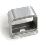
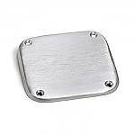
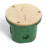
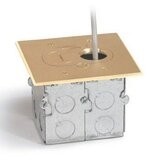
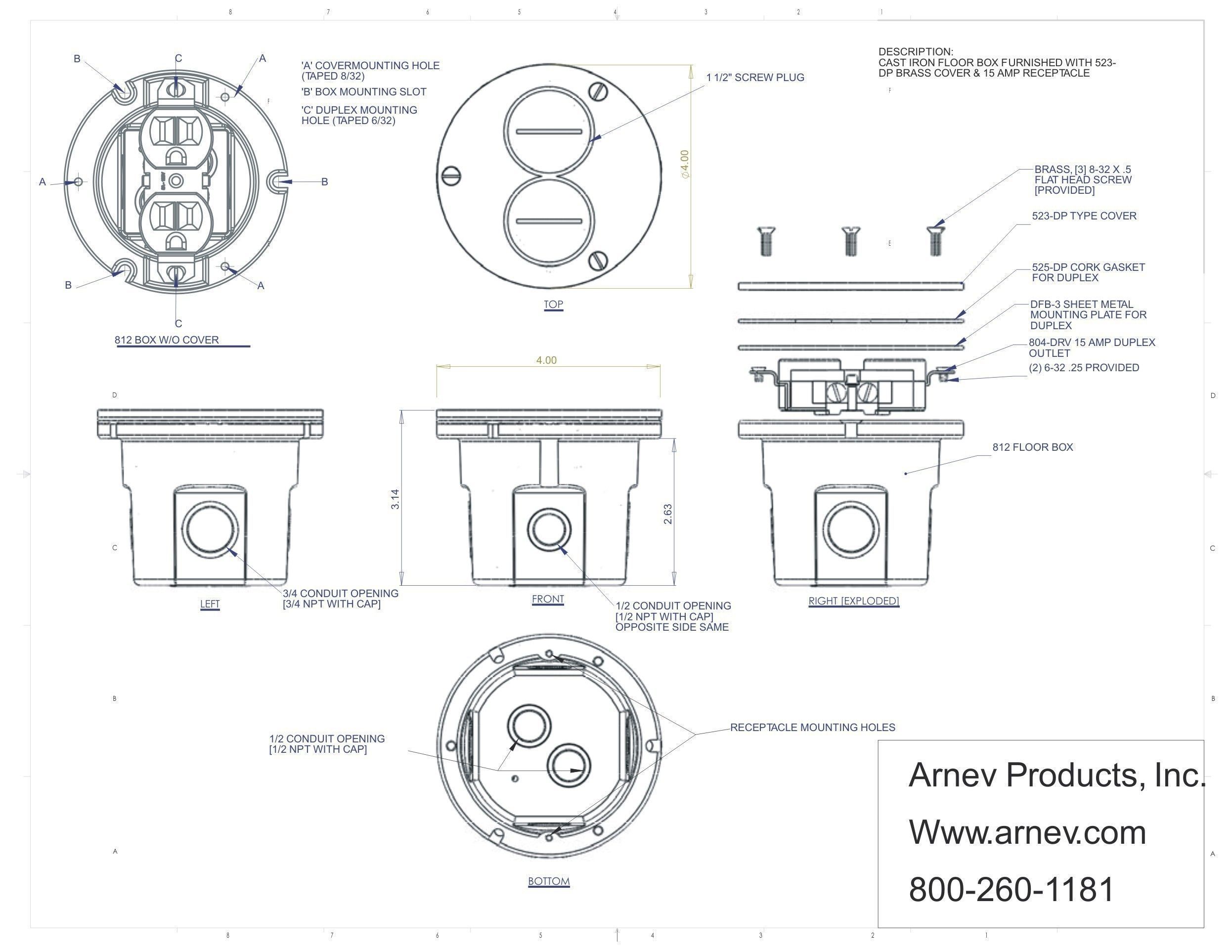
This floor box is furnished with a Nickel Silver cover & a 15A Receptacle, and a Very heavy-duty cast iron box. Can be used for both Wood and Concrete floors. Additional covers that work with these boxes are the AP-TCP Series at 5-3/4 inch round in brass and aluminum or our AP-PFC series heavy plastic covers. Also, the AP-812-MKM double-hole saw is a convenient method for cutting the wood floor, as it's almost mistake-proof!
(Size: 4" x 3-1/8" 14.5 cu. in. interior)
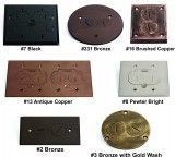
Available 4" covers for this box above. Solid Brass, Aluminum, and some Nickel Silver
|
4'' Cover (1/8'' Thick) with
(2) 1-1/2'' Screw Plugs for
Duplex. Flush Mount.
|
Floor Box Cover for Concrete
Floors 4'' Cover (1/8'' Thick)
with (2) 1-1/2'' Screw Plugs
for Duplex
|
for Single Receptacles and
Concrete Floors 4'' Cover
(1/8'' Thick)
|
Cover for Concrete Floors
in Brass and Aluminum Dual
Hinged 4'' Cover
(1/4'' Thick) for Duplex
|
in Brass and Aluminum for
Concrete Floors Hinged 4''
Cover (1/4'' Thick) for Duplex
|
Box Cover Brass and
Aluminum for Concrete
Floors but for Decora
Receptacle
|
Box Cover Floor Box for
Telephone, for Concrete
Floors in Brass and Aluminum
|
|
812-DFB SERIES
Installation Instructions
1. For wood floors
a. Using a 4” hole saw, cut the flooring to a depth equal to the thickness of the cast
flange and cover assembly being used on the floor box.
b. Center a 3.5” hole saw in the 4” opening and cut through all remaining layers of flooring.
This will create a lip for the flange of the box to rest on.
c. Remove the cover assembly and wiring device from the floor box.
d. Dropbox body into the opening and secure using #6 wood screws (not provided) through
the countersunk slots in the cast flange and into the underlying wood.
e. After wiring and installing electrical or communication devices to the floor box and ground
screw (if applicable), replace the cover plate assembly using #8/32 x ½” screws provided.
f. If an uneven cut was made into the flooring, goof rings (TCP-GR1) can be used in conjunction
with the original cover assembly or oversized covers (TCP series) can be used in place of the
original cover assembly.
g. For carpeted areas, use SCF-1 placing on top of the floor box (cover assembly removed first),
then insert the cover assembly into the carpet flange. Use 1.25” longer screws provided through
the cover assembly and that will affix to the floor box.
h. For tile applications, order part #812 (box body only) and a TCP-style cover. Follow steps a-d
above. After wiring in step e, install the mounting plate and gasket, then place the TCP style plate
on top of the floor and use #8/32 X ¾” screws provided.
2. For concrete floors
a. Not recommended for new construction as no concrete cap is provided and this is a nonadjustable box.
b. Core out 4 ¼” into concrete as deep as needed to accommodate the height of the box and the ability to
affix conduit from underneath.
c. Backfill concrete if necessary to close gaps in the floor.
d. Follow steps c-h above.


